As classrooms offer more remote learning options and workplaces become more flexible, the demand for multiple cameras for video conferencing is growing. The Nureva® HDL410 system integrates with the INOGENI® CAM230 camera selector to enable automatic camera switching in multi-camera rooms.
This integration equips multiple cameras with switching capabilities based on these camera zones, improving the room’s overall camera coverage and the experience for remote participants. Camera zones are set up using the Nureva app or Nureva Console. This article focuses on setting up the integration using Nureva Console.
Step 1: Placement, connections and network access
System placement
For the HDL410 system to provide the most accurate sound location data, Nureva recommends the microphone and speaker bars be installed on opposite or perpendicular walls. This positioning produces accurate X and Y data.
Recommended installation positions are shown in the diagrams below.
|
|
|
|---|---|---|
|
|
|
.png)
.png)
.png)
.png)
.png)
.png)
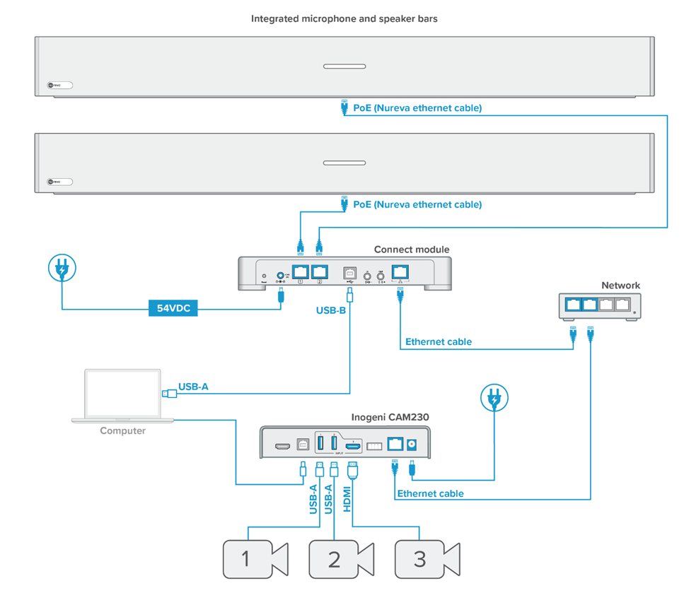
Hardware connections
Connect the HDL410 and CAM230 as shown in the connection diagram below.
Learn more about connecting HDL410 system components
Network access
Data is exchanged between the HDL410 connect module and the CAM230 to facilitate camera switching. The connect module and CAM230 must be connected to the same network for the data exchange to happen.
INOGENI recommends reserving an IP address on the network for the CAM230. Using the reserved IP address will help with the initial setup and maintain communication between the CAM230 and the HDL410 connect module.
Explore reserving an IP address
Step 2: Update CAM230 firmware
Important: The CAM230 should use firmware version 2.10 or later for this integration. Using firmware versions earlier than 2.10 may have unexpected results.
INOGENI offers a web portal for the configuration and management of the CAM230. The firmware is updated using this web portal and a downloaded file.
The CAM230 and computer must be on the same web portal network to make a connection. An alternative option is to connect the computer directly to the CAM230. If the web portal or computer does not recognize the CAM230, try the following:
Ensure the CAM230 is assigned to a reserved IP address on the network.
Confirm the computer and CAM230 are connected to the same network.
Power cycle the CAM230.
Check the Ethernet cable connections.
Try different Ethernet cables.
Check the USB cable connection between the computer and CAM230.
Logging in to the CAM230 web portal
Access the web portal by entering the IP address 169.254.10.10 into a browser.
Complete the login with username admin and password admin.
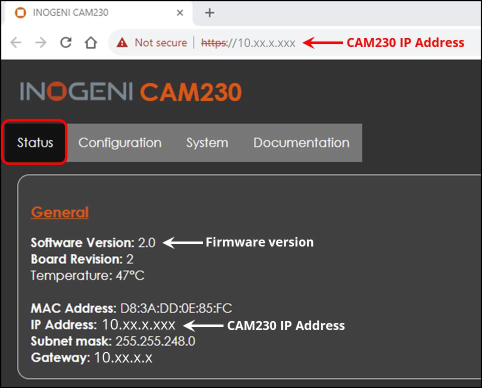
The portal will open showing the Status tab.
The information shown under General includes the firmware version and the CAM230 IP address.
Check the firmware version in the Status tab.
If the firmware is earlier than version 2.2, go to the CAM230 resources webpage.
Go to the Firmware section at the top of the page.
Click the most recent firmware release.
A zip file will download containing the WIC file and release notes.
Extract the zip file.
Installing the firmware update
From the CAM230 web portal, select the System tab.
Scroll to the Update section at the bottom of the portal.
Press the Choose File button and select the extracted WIC file.
Click the Update CAM230 button to begin the update.
The firmware update will take up to 1 minute to complete.
After the update, the CAM230 will restart and the portal will refresh.
Important: The CAM230 and the computer must be connected to the same network.
Step 3: Obtain a REST API access token
A REST API access token is needed in Step 5 of setting up this integration. This token is generated in the CAM230 web portal. If a token has already been created, the existing token can be looked up.
Generate a new REST API access token
Select the System tab.
Go to the Security section at the top of the page.
Press the Generate REST API access token button to generate the token.
Important: Keep the web portal open to copy and paste the token during Step 5. If a new REST API token is generated, update Nureva Console with the new token.
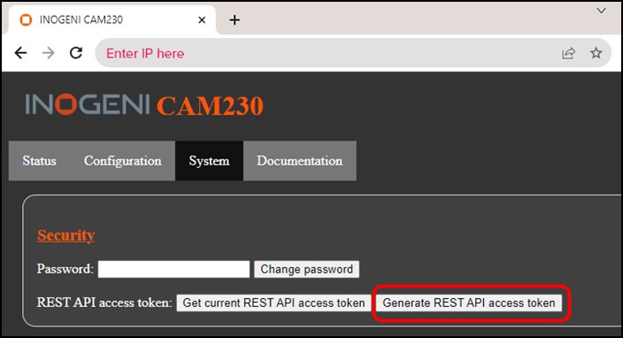
Look up existing REST API access token
Select the System tab.
Go to the Security section at the top of the page.
Press the Get current REST API access token button.
A new web page will open and show the REST API access token.
Copy the token from this page.
Press the back button on the browser to return to the CAM230 web portal.
Step 4: Enroll HDL410 and update firmware
Enrolling an HDL410 system
The HDL410 system must be enrolled in Nureva Console to configure the CAM230 integration. If the HDL410 system is already enrolled, advance to updating the firmware.
Updating the HDL410 firmware
To ensure optimum audio quality and access to the latest features, the HDL410 firmware must be up to date. If the firmware is already up to date, advance to the next step.
Update HDL310 and HDL410 system firmware
Step 5: Enable camera switching integration
The camera switching integration is managed using Nureva Console.
Note: INOGENI recommends reserving an IP address on the network for the CAM230. Using the reserved IP address will help with the initial setup and maintain communication between the CAM230 and the HDL410 connect module.
From the Rooms dashboard, open the room with the HDL410 and CAM230.
Select the HDL410 system to open the Devices dashboard.
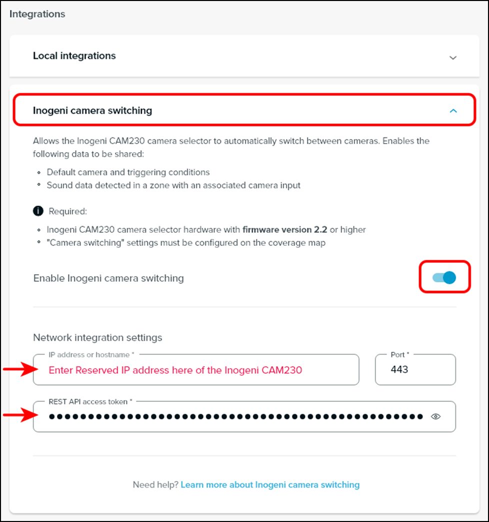
Scroll down to Integrations and expand the menu.
Enable INOGENI camera switching by moving the toggle to the right.
Enter the IP address or the hostname.
Port 443 is the default and will apply to most integrations.
Copy and paste the REST API access token that was generated in Step 3.
Press the Apply button at the top of the Devices dashboard.
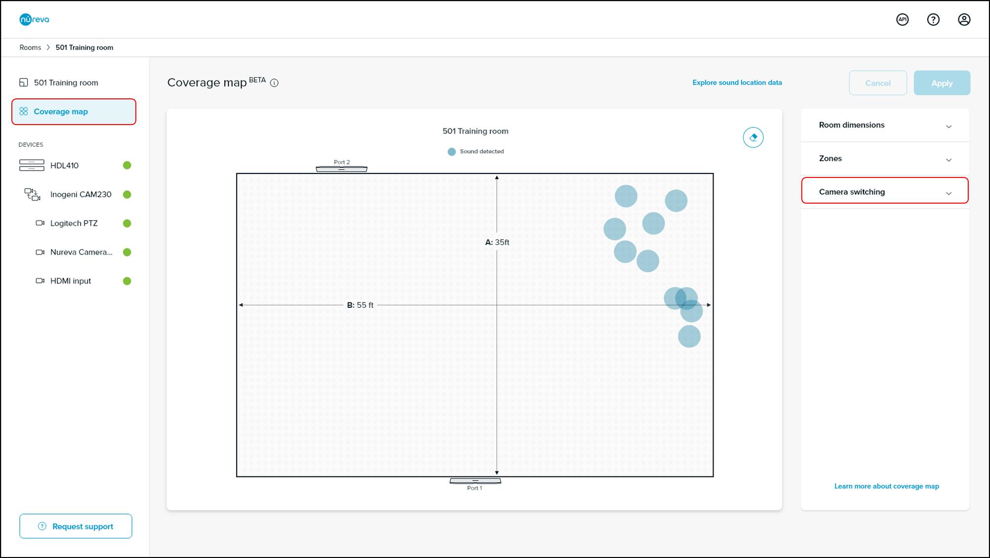
Open the Coverage map. If the CAM230 integration has successfully been set up, camera switching controls will be available. The HDL410, CAM230 and connected cameras will be shown under Devices. These devices can also be monitored from the Rooms dashboard.
If the camera switching controls are unavailable, check that the IP address and REST API access token have been entered correctly. Also, confirm that the HDL410 and CAM230 are switched on and connected to the same network.
Step 6: Confirm placement and room dimensions
The HDL410 system generates a coverage map that shows the placement of the system as well as the room size. The blue circles on the coverage map indicate where sound location data is being generated within the room. To ensure accurate camera switching, the system placement and room size must be shown accurately on the coverage map.
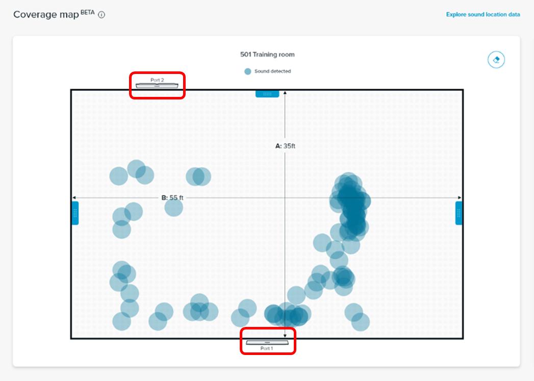
Confirm system placement
The coverage map should show the positioning of the microphone and speaker bars as they are in the room. If the coverage map placement and the actual placement do not match, the system should be calibrated. Sound location data may not appear if sound is not generated in a room.
The following steps are taken to perform calibration through Nureva Console. Make sure there are no audible sound sources in the room other than normal ambient noise (e.g., no music playing, no people talking).
Go to Device settings.
Select Audio processing.
Under the calibrate section, click Start.
When the calibration signal stops and the indicator lights return to a normal state, the calibration is complete. The HDL410 system placement on the coverage map should now represent the actual placement in the room.
Learn more about system calibration
Adjusting room dimensions
The maximum area represented by the coverage map is 35' x 55' (10.7 x 16.8 m), which is the default area. The coverage map area can be changed to better represent the actual room size. Two options are available for adjusting the room dimensions.
Move the drag handles on the coverage map to the correct room dimensions.
Use the room dimension fields on the right side of the dashboard.
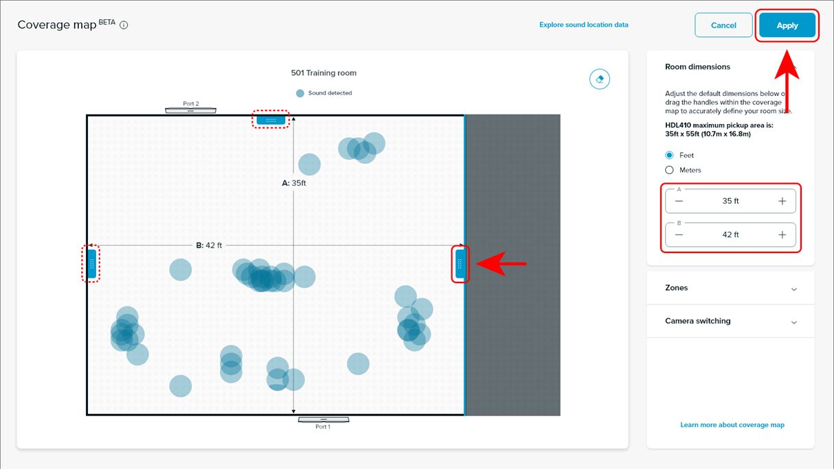
Adjust the room dimensions to accurately match the room size. When the room dimension adjustments are complete, press the Apply button.
Important: Ensure the room dimensions are correct before pressing Apply.
After the edits have been applied, the coverage map will return to a zoomed-in view and exclude any sound location data outside of the updated dimensions. The room dimensions can be edited again at any time by pressing the Edit room size button.
Step 7: Create coverage map zones
A zone defines an approximate area within a room. The data to map each zone, as well as the indication of when a sound is detected within each zone, is sent to the CAM230 to facilitate camera switching.
Creating a zone
Open the Zones accordion on the coverage map page.
Press the Create zone button.
A zone will appear at the center of the coverage map.
Drag the zone within the coverage map to the required location in the room.
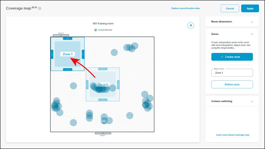
5. Adjust the zone to the required size using the drag handles.
6. Edit the zone name to associate it with the camera’s input and coverage. For example, if Camera 1 is focused on the audience, use Audience for the zone name.
7. Press Apply to save the zone.
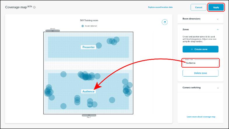
Zones can be deleted at any time by opening the zones accordion, selecting the zone from the coverage map and then pressing the Delete zone button.
Testing zones
Zones can be tested by speaking in each zone area within the room. It is recommended the tester speak for at least one minute while moving to all the edges of the zone being defined. As sound location data is captured and displayed on the coverage map, it will help confirm the zone position and size. The sound location data refreshes every minute.
Adjust the zone size and position if required. All sound data above 45 dB will be shown on the coverage map but only data above 60 dB for a specified length of time will be used to initiate a camera switch. A zone cannot be applied if:
It’s positioned outside the room borders.
It’s overlapping with another zone.
It doesn’t have a name.
It has a name that’s being used for another zone.
Its name exceeds 50 characters.
Step 8: Configure camera switching settings
Configure camera switching
Open the Camera switching controls. All camera inputs will be visible, even if all camera inputs are not being used.
Select the default camera from the Default camera pull-down menu. This is the camera that the CAM230 switches to whenever voices are not detected. The default camera value in the example below is the camera assigned to USB Input 1.
Match the zones with each camera input using the pull-down menus. Available options are Audience, Presenter and Podium.
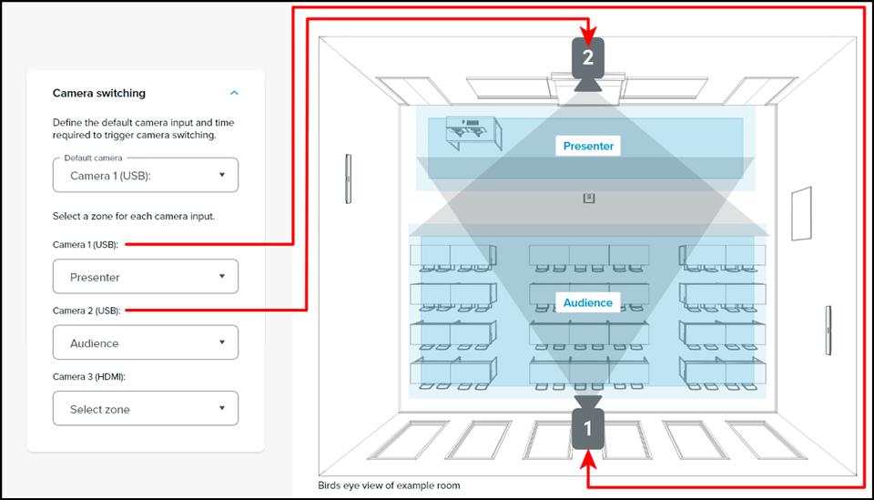
In this example, Camera 1 is associated with the presenter and Camera 2 is associated with the audience.
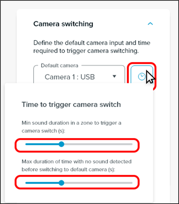
Adjusting camera switching time triggers
The INOGENI CAM230 will activate camera switching when a sound has been detected in a zone for a specific length of time. The time can be adjusted to suit the needs of the room. The minimum time duration of sound to trigger a camera switch is 1 second. The CAM230 will switch to the default camera when no sound has been detected for 5 seconds.
The time variables can be adjusted by pressing the Time icon.
Use the sliders to set:
The minimum sound duration to trigger a camera switch.
The maximum time to wait before switching to the default camera.
Slider adjustments can be made with the arrow keys on the computer keyboard.
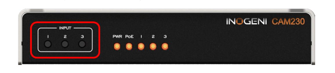
Turning off automatic switching
To turn off automatic camera switching, press the input button on the CAM230 for the corresponding camera. Automatic camera switching can be resumed by pressing the same input button.
Automatic camera switching can turned on and off during a conference call. When the conference is over, the CAM230 will return to automatic switching.
CAM230 status lights
The CAM230 has status lights on the front of the device. These lights help determine the status of the device and can be used to help troubleshoot.
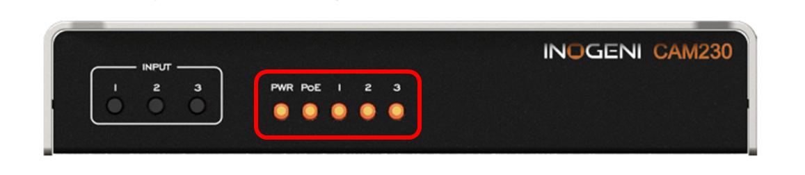
Power input (PWR) | Power over Ethernet (PoE) | Input lights (1, 2, 3) |
|---|---|---|
|
|
|
Troubleshooting
HDL410 system
General issues
Ensure the firmware is up to date.
Power cycle the connect module.
Check the cables between the connect module and the microphone and speaker bars.
Check the USB cable between the computer and connect module.
Coverage map and zones
Confirm the HDL410 system is placed as shown in Step 1.
Ensure the HDL410 is the default audio device for the operating system.
CAM230 camera selector
General issues
Power cycle the CAM230.
Check the Ethernet cables.
Check the USB cable.
Device detection issues
Confirm the firmware is version 2.2 or later.
Ensure the CAM230 is assigned to a reserved IP address on the network.
Confirm the computer and CAM230 are connected to the same network.
An alternative option is to connect the computer directly to the CAM230.
Ensure the cameras are on the same network.
Check the cables and connections to the cameras.
Tip: If configuring the integration during a videoconferencing call, it is recommended the call is ended and a new one is started before testing the setup.