Recommended room sizes
HDL300 | Dual HDL300 |
|---|---|
Maximum: 25' x 25' (7.6 x 7.6 m) | Maximum: 30' x 50' (9.1 x 15.2 m) |
HDL310 | HDL410 |
Maximum: 30' x 30' (9.1 x 9.1 m) | Maximum: 35' x 55' (10.7 x 16.8 m) |
Recommended installation height
When considering the installation height for your setup, aiming within the range of 7 feet (2.2 meters) to 10 feet (3.0 meters) is generally recommended.
However, installing slightly below the minimum height can still yield satisfactory performance, especially if it’s needed for the room layout. Experimenting within the range will help determine the best spot for the specific environment.
Installation note: When mounting the bar close to the ceiling, allow an extra 1" (2.5 cm) above the screws to accommodate upward hooking during installation.
Microphone clearance
The microphone array is on the bottom edge of the microphone and speaker bar. Ensure adequate clearance between the bottom of the bar and any objects directly below it.
|
|
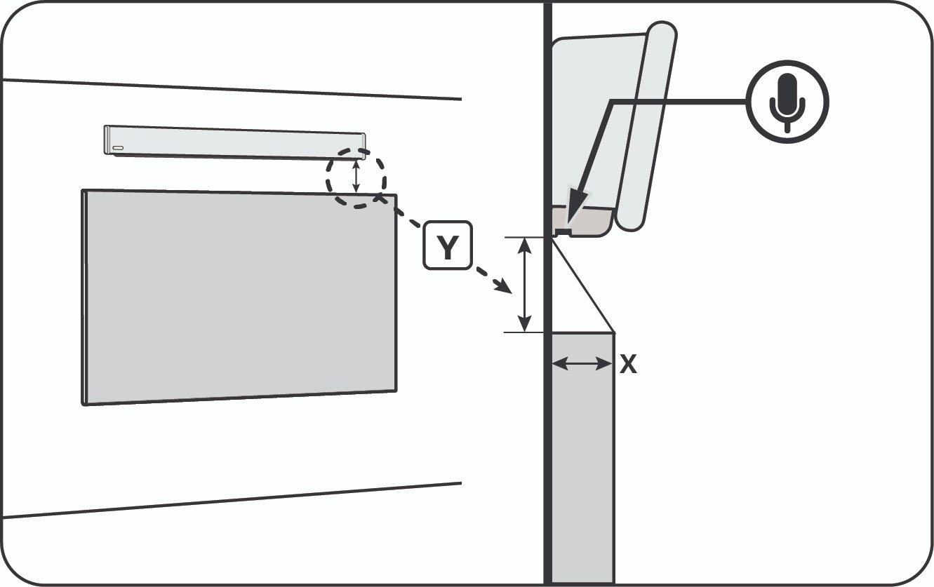
The clearance is calculated as a 3:2 ratio. The object’s depth (the X value) is multiplied by 1.5 to see how much space is needed between the microphones and the object below (the Y value).
Example: A wall-mounted LCD display is below the microphone and speaker bar.
Depth (X) = 3" (7.6 cm)
3" x 1.5 = 4.5”
The microphone clearance (Y) is 4.5" (11.4 cm).
Recommendations
Do not install the integrated microphone and speaker bar above hardware with fans. Hanging the product above hardware with fans can cause interference with the microphone pickup.
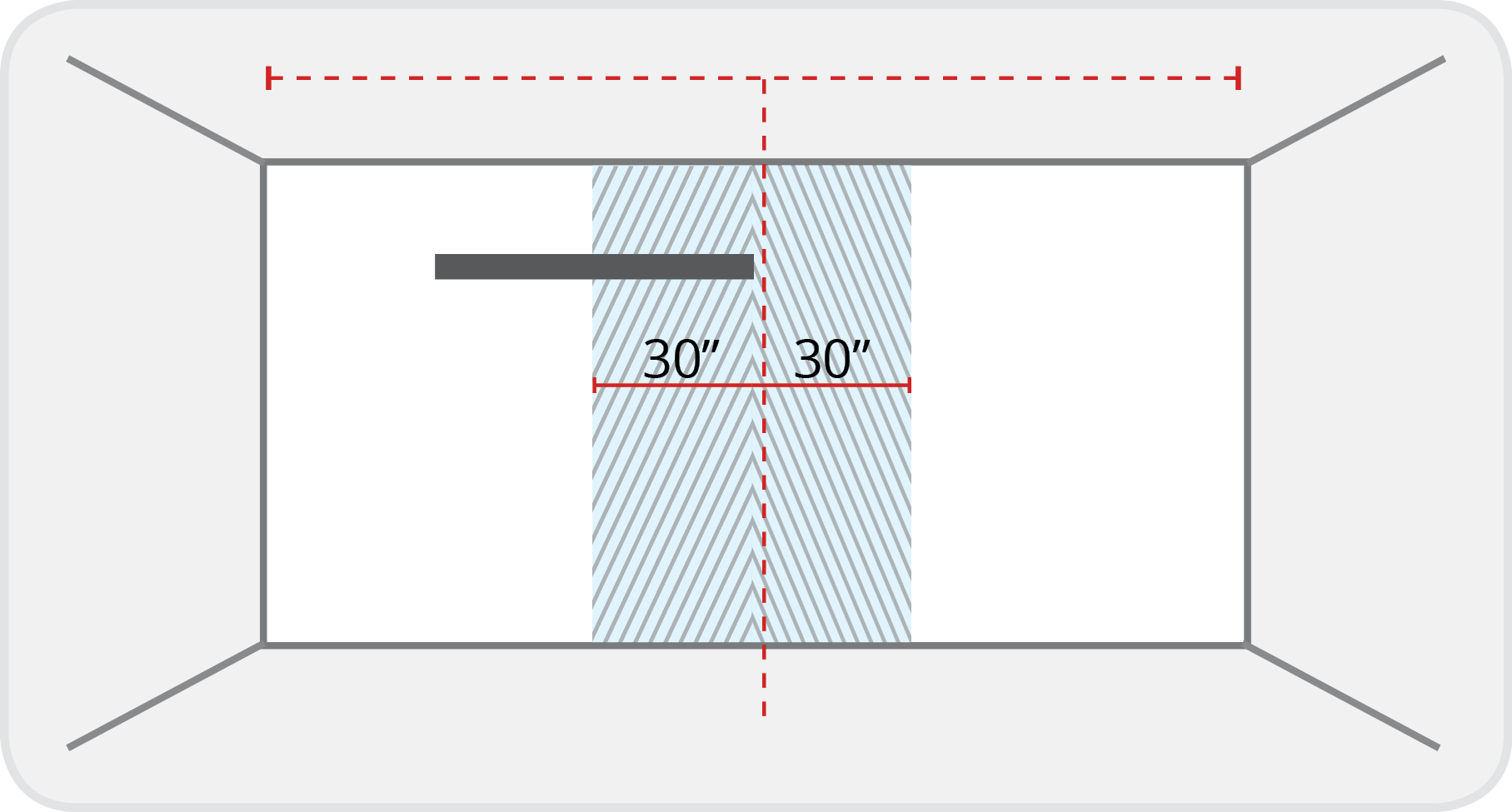
Allow for adequate space between the ends of the microphone and speaker bar and the corners of a room. Installing the microphone and speaker bar against a corner will impede microphone pickup. It is recommended to leave 3.0' — 5.0' (0.9 — 1.5 m) from the edge of a microphone and speaker bar to the corner of a room.
For HDL310, HDL300, and Dual HDL300 systems, place the microphone and speaker bar within 30 inches (76 cm) of the wall's center. For HDL410 systems this applies if the microphone and speaker bars are mounted on opposite shorter walls of the room.
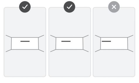
The microphone pickup relies on a direct sound path from the person speaking and audio reflected from the mounting surface. When mounting flush to the wall is not an option, using a backboard can help ensure proper microphone pickup.
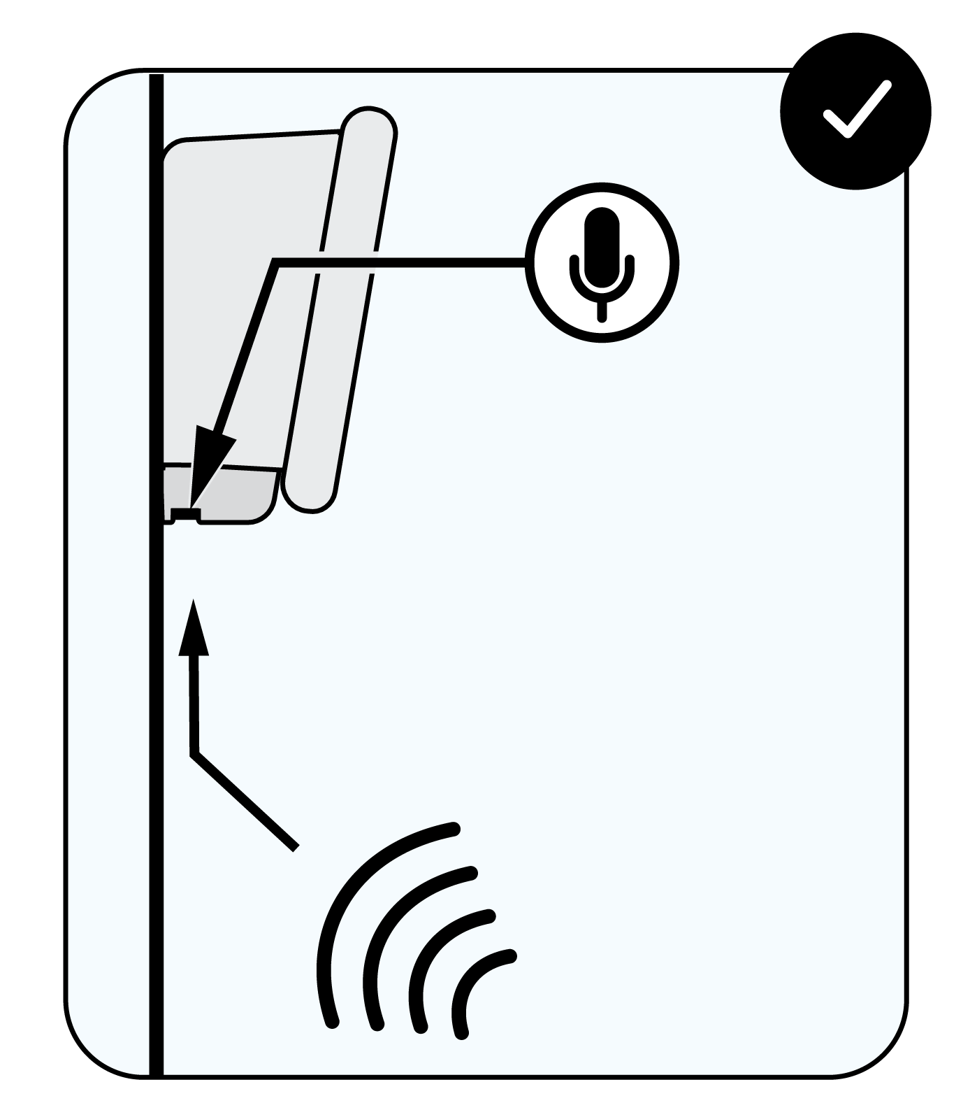
Side view of the bar mounted flat against the wall for optimal sound reflection.
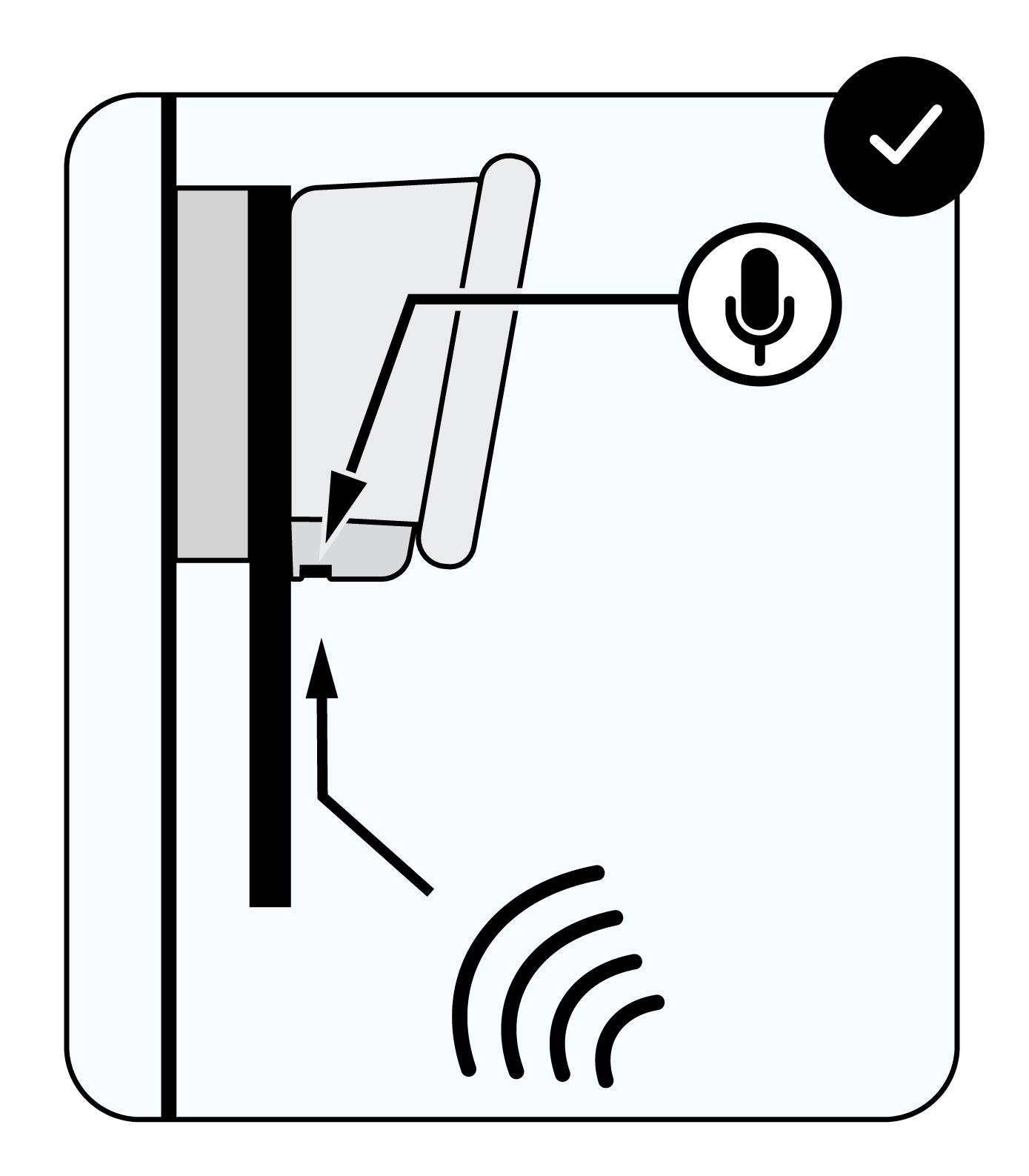
Side view of the bar mounted with a backboard for better sound reflection.
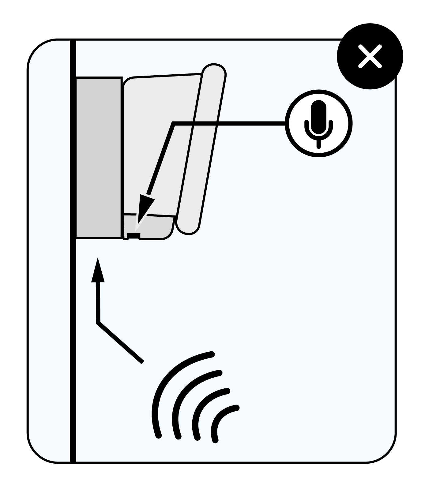
Side view of the bar mounted on a raised surface, not flush with the wall. This setup reflects minimal sound.
Do not install the microphone and speaker bar directly onto soft surfaces, such as acoustic panels or fabric wall coverings. Installing on a hard surface provides the best microphone pickup. Using a backboard to mount the microphone and speaker bar onto soft surfaces can help ensure proper microphone pickup.
Avoid installing the microphone and speaker bar in recessed areas. Placing the bar in a recessed area of a room will negatively affect the microphone pickup.
For Dual HDL300 systems leave about 20 to 25 feet (6.1 to 7.6 meters) between the microphone and speaker bars, measured from center to center. Some overlap in their range is ideal, but spreading the units out improves microphone coverage. The distance between the HDL410 microphone and speaker bars can be up to 30' (9.1 m) depending on the desired room coverage.
HDL410 placement guide
The HDL410 features Microphone Mist™ technology which has built-in flexibility for placing the HDL410 microphone and speaker bars. The guidelines offered in this placement guide will help ensure an optimal audio experience.
Learn more about HDL410 microphone and speaker bar placement.
Mounting a system with a backboard
Installing a Nureva audio system flush to a wall is not always an option. The optimal installation location could turn out to have a surface that’s challenging or not large enough. Using a backboard to mount the microphone and speaker bar in these situations can help ensure proper microphone pickup.
Learn more about using a backboard with an HDL300, Dual HDL300, HDL310 or HDL410 system.